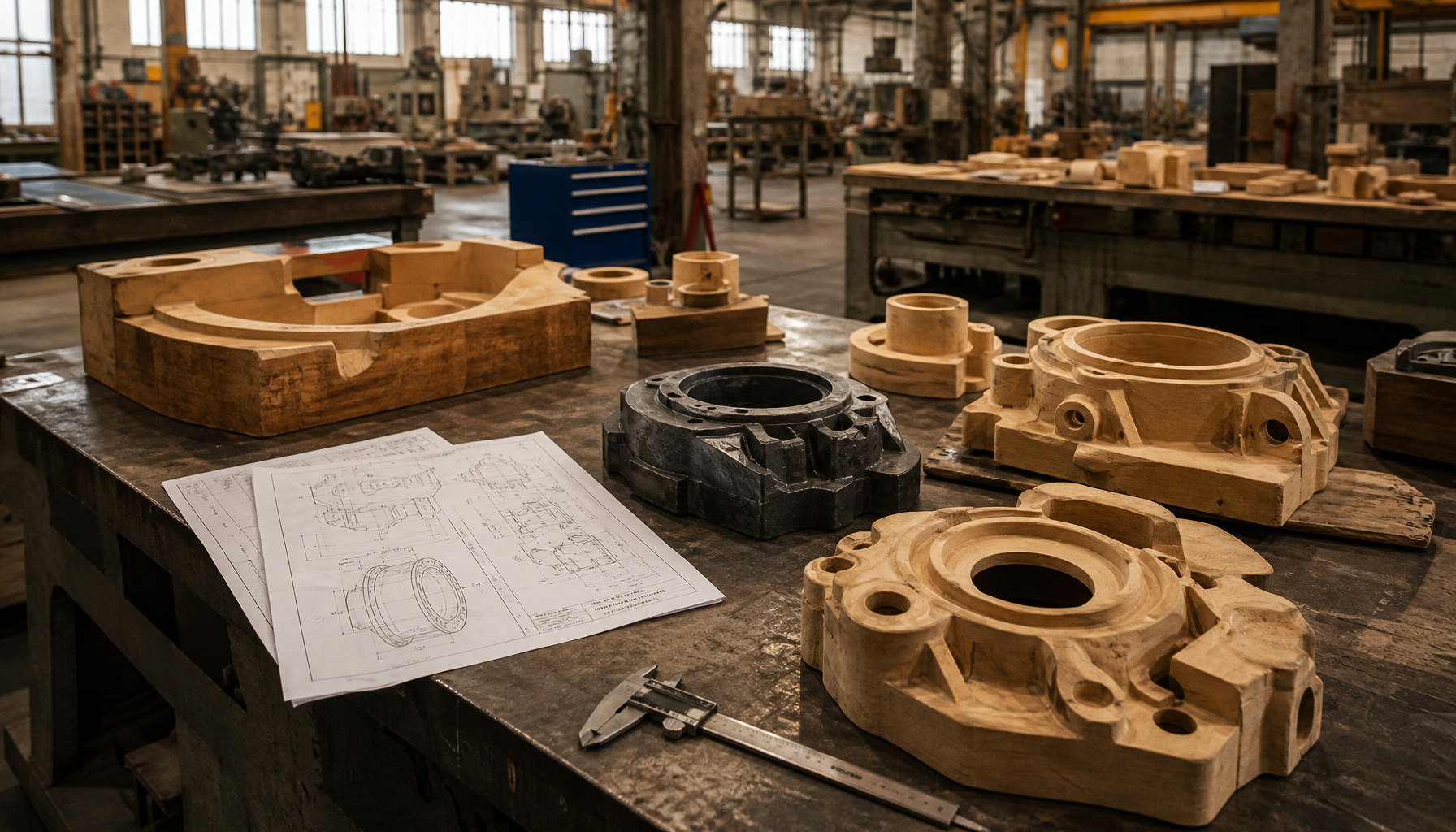
Here's a number that has cost OEM buyers more money than any other single figure on a foundry drawing: 1.04%.
That's 1/8 inch per foot. It's the most commonly quoted shrink rule for grey iron, and it's the rule most pattern shops reach for without thinking. Get it right and nobody says a word. Get it wrong and you're looking at a first article that misses the fixture by 4 mm on a 500 mm bore, a three-week tooling delay, and a machining allowance that's been quietly eaten before the part ever reached the CNC.
In the pattern drawings that come across our desk, roughly one in eight dimensional first-article failures traces back to a shrinkage allowance decision. Not to a machining error. Not to a bad core. Just the number the patternmaker wrote in the corner of the drawing.
This is the chart you should keep next to your RFQ pack, and the explanation of what sits underneath it.
First, the part that most shrinkage charts leave out
Almost every shrinkage table you'll find online gives you one number per material. That number is the patternmaker's contraction, and it covers exactly one of the three shrinkages happening inside your mould.
The other two are the foundry's problem, not yours — but you need to know they exist, because the difference explains why two foundries quote you different numbers for the same part.
| Shrinkage type | What it is | Who compensates for it | Typical magnitude (grey iron) |
|---|---|---|---|
| Liquid shrinkage | Molten metal contracting as it cools from pouring temperature to the freezing point | Risers / feeders | Small, often near zero |
| Solidification shrinkage | Volume change as liquid turns to solid | Risers, chills, padding | 3–6% volume, offset by graphite expansion |
| Solid contraction | The solid casting continues to contract from freezing to room temperature | The pattern — this is your shrink allowance | 0.8–1.0% linear |
That third row is the one on your chart. Everything above it is riser design — which is why a good foundry can fix porosity with a feeder but can't fix a dimensional miss with anything except a new pattern.
If a supplier tells you "our shrinkage is 0.9%," ask which of these three they mean. The answer often shows the person hasn't separated them.
The iron casting shrinkage allowance chart

Below is the working chart. These are ranges, not points — and the ranges are wide on purpose, because the right number for your part depends on section thickness and restraint, which we'll get to in a minute.
| Material | Linear shrink (%) | Shrink rule (in/ft) | Notes |
|---|---|---|---|
| Grey iron (Class 20–40) | 0.8 – 1.0 | 3/32 – 1/8 | Flake graphite expands during freezing and offsets contraction. Thick sections run low. |
| Ductile iron (60-40-18, 65-45-12) | 1.0 – 1.4 | 1/8 – 5/32 | Nodular graphite doesn't expand like flake. Higher allowance, and more riser demand. |
| Austempered ductile iron (ADI) | 1.2 – 1.5 | 5/32 – 3/16 | Alloy content pushes it above standard ductile. |
| Malleable iron | 1.0 – 1.5 | 1/8 – 3/16 | White iron as-cast, so pattern must anticipate the annealing step. |
| White iron / high-chromium | 1.5 – 2.1 | 3/16 – 1/4 | No free graphite. Contracts nearly like steel. |
| Ni-Hard (Type 1–4) | 1.8 – 2.2 | 7/32 – 1/4 | High carbide content. Very sensitive to section size. |
| Carbon steel (WCB, WCC, LCC) | 2.0 – 2.4 | 1/4 – 9/32 | The classic "1/4 inch per foot" rule. |
| Low-alloy steel (WC6, WC9) | 2.0 – 2.5 | 1/4 – 5/16 | Alloying widens the range. |
| Austenitic stainless (CF8, CF8M) | 2.4 – 2.9 | 5/16 – 11/32 | Highest thermal expansion of the common ferrous family. Restraint matters a lot here. |
| Martensitic stainless (CA15, CA6NM) | 2.0 – 2.4 | 1/4 – 9/32 | Similar to carbon steel. |
| Aluminium, sand cast | 1.0 – 1.3 | 1/8 – 5/32 | Included for comparison — sand moulds restrain aluminium less than expected. |
Treat the top of each range as the safe default for a first pattern and the bottom as something you earn with data. If a foundry quotes you the bottom number on their first quote, ask what test casting backs it up.
Paste the two relevant rows into your RFQ pack and name the factor you're working to. A supplier who sees the number on paper will quote against it. A supplier who doesn't will quote against whatever their shop defaults to — and that's how two "identical" quotes end up 40% apart on tooling cost.
Converting a shrink rule to a percentage (and why buyers get burned here)
Pattern shops in different regions express the same allowance in different units, and drawings occasionally carry both. The conversion is trivial but the consequences of fumbling it are not.
Percentage = (inches per foot ÷ 12) × 100
| Shrink rule | Percentage | Common for |
|---|---|---|
| 1/32 in/ft | 0.26% | Not used in practice for ferrous |
| 1/16 in/ft | 0.52% | Heavily restrained grey iron sections |
| 3/32 in/ft | 0.78% | Grey iron, thick wall, cored |
| 1/8 in/ft | 1.04% | Grey iron default; ductile iron low end |
| 5/32 in/ft | 1.30% | Ductile iron default |
| 3/16 in/ft | 1.56% | White iron, high-alloy ductile |
| 7/32 in/ft | 1.82% | Ni-Hard |
| 1/4 in/ft | 2.08% | Carbon steel, the classic rule |
| 9/32 in/ft | 2.34% | Low-alloy steel |
| 5/16 in/ft | 2.60% | Austenitic stainless, low end |
| 11/32 in/ft | 2.86% | Austenitic stainless, high end |
Where this bites: your drawing note says "shrink 1.04%." The pattern shop's CAD operator reads it, applies a 1/8 shrink rule to the pattern layout, and considers the job done. On paper those are identical. In practice, if the CAD model was already scaled and the shrink rule is applied again to the pattern, you've now got 2.08%. On a 400 mm dimension, that's an 8 mm oversize. Nobody catches it until the CMM report lands.
One number, one place. Write it into the PO as "pattern to be scaled by 1.04% linear from the 3D model; no secondary shrink applied to pattern layout." It's a boring sentence that has saved people five figures.
Why the chart alone is not the answer
A shrinkage chart gives you a starting point. What actually happens in the mould is a negotiation between the metal and everything holding it back.
Mould restraint
Free contraction is what a metal does when nothing stops it. Castings don't have that luxury. Cores, ribs, flanges and thick-to-thin junctions all restrain contraction, and the measured contraction on a real part is commonly 30 to 50% lower than the free value.
This is why some grey iron jobbing shops pattern at 0.6% instead of 1.0%. The part is boxy, it's cored, and it physically cannot pull in the way the chart says it should.
Sit in on a conversation between a patternmaker and a foundry metallurgist and you'll hear exactly this argument. As one Illinois pattern shop foreman put it when we asked about a pump housing job: "The chart says an eighth. The part says a sixteenth. I've made this shape before and I know what it does."
That's not sloppiness. That's accumulated evidence. The chart is the hypothesis; the part is the experiment.
Section thickness and modulus
Thick sections cool slowly. In grey iron, slow cooling gives the graphite more time to expand, which eats into net contraction. So a 75 mm section and a 6 mm rib on the same casting want different allowances — and they can't have them, because there's one pattern.
The practical compromise: pattern to the dominant dimension. If the critical-to-function feature sits in a thick boss, allow slightly lower. If it sits on a thin flange that will cool fast and pull hard, allow slightly higher.
Carbon equivalent and chemistry
For grey iron, higher carbon equivalent means more graphite, which means more expansion and less net shrink. Push CE toward eutectic (around 4.3) and you can shave 0.1–0.2 points off the allowance. Drop CE for strength and you add it back.
If your supplier changes the charge mix between the sample casting and production — which happens more than anyone admits — your shrinkage behaviour changes with it.
Moulding medium
Green sand compacts and dilates differently from chemically bonded no-bake sand or shell. Green sand moulds tend to move under pouring pressure, which shows up as an apparent extra shrinkage that isn't metal contraction at all. A supplier who runs the same part in a different moulding line can produce a dimensional shift without changing a single line of the drawing.
This is one of the reasons we ask suppliers which line a part will run on before we accept a shrink factor. Our casting technical notes cover the moulding-line comparisons in more detail if you want the process side.
Pouring temperature
Pour hotter and you add superheat, which the risers have to handle and which shifts the cooling curve. It rarely changes the final linear contraction by more than a tenth of a percent, but on a 1.5 m dimension that's still 1.5 mm.
The cheap way to de-risk an uncertain shrink factor
If the chart says 0.8–1.0%, your part is boxy and cored, and it measures 900 mm across, you don't have to guess — and you don't have to commit to production tooling to find out.
Print two pattern sets. Scale one at the bottom of the range and one at the top. Pour a sample from each, then measure the same critical dimension on both. On a part that size you're looking at a few hundred dollars of printed pattern and two pours, against a re-pattern that runs into five figures and six to twelve weeks.
Two rules make the test worth anything:
- Pour both samples from the same heat, on the same moulding line. Change the chemistry or the sand between them and you've tested the variables, not the shrink factor.
- Measure the same three dimensions on both, at the same temperature. You're looking for a linear difference between the two, not an absolute number.
Whichever sample lands closer on the dimension that matters becomes your production factor. The other one tells you how much margin you had — useful the next time somebody in a cost review asks whether the machining allowance can come down.
The same logic covers a correction on an existing pattern. If the first article comes out 0.4% small, the CAD can be rescaled and reprinted in days; the pattern block doesn't have to be re-cut. Ask the foundry which of their tooling paths allows that before you place the order, not after the first article fails.
Machining allowance is a separate line — don't let them merge
This is one of the most common dimensional failures on ferrous castings, and it's a paperwork problem, not a metallurgy one.
Shrink allowance makes the pattern bigger so the casting lands on nominal after it cools. Machining allowance makes the pattern bigger again, on the surfaces you're going to cut, so there's stock left for the tool. Both are additions. They stack.
Typical machining allowance per ISO 8062-3 ranges:
| Nominal dimension | Typical machining allowance (per surface) |
|---|---|
| Up to 50 mm | 1.5 – 2.5 mm |
| 50 – 120 mm | 2.5 – 3.5 mm |
| 120 – 250 mm | 3.5 – 5 mm |
| 250 – 500 mm | 5 – 8 mm |
| 500 – 1000 mm | 8 – 12 mm |
| Over 1000 mm | 12 – 20 mm |
Where it goes wrong: someone adds machining allowance to the as-cast CAD model, exports it, and then the pattern shop scales the whole thing by the shrink factor — including the allowance. Now the allowance is 1–2% bigger than intended, and on a 15 mm allowance that's no big deal. Reverse the order and double-apply, and on a tight casting you can end up with an oversized part and a machining operation that has to cut an extra pass.
The fix is unglamorous: state the sequence on the drawing. "Apply shrink to the nominal 3D model. Add machining allowance to the scaled pattern. Do not re-scale."
What to check on the pattern drawing before you sign it off
Before the pattern is cut, eight things need to be visible on the drawing pack. If any of them is missing, you're gambling on the supplier's default assumptions — and defaults are where money disappears.
- The shrink factor stated as a number. Not "1/8 rule." Write 1.04% (or whatever you've agreed). Units and value, every time.
- Where it was applied. To the 3D model, to the pattern layout, or to both. One of those three is correct and two of them are expensive.
- Machining allowance dimensioned separately per surface, with the ISO 8062-3 grade stated if you're using one.
- Draft angle noted per surface. Shrink and draft interact — pulling draft out of a shrunk model is a different operation from pulling draft out of a nominal one.
- Core prints and core box shrinkage. The core shrinks too, and on a cored bore the core and the mould are both contracting in the same direction, which can double the error or cancel it depending on geometry.
- Any local deviations from the global factor. Thin ribs, long unsupported spans, and thick bosses sometimes get a modified local allowance. If they did, you want to know where and why.
- The datum scheme for the first article. If the CMM is going to measure from a datum that moves with the shrink, you'll get a report that looks fine and a part that doesn't fit.
- Test coupon location and traceability. Your mechanical properties come from a test bar poured with the part. Where it sits in the mould affects what it reports.
The 5-minute first-article check that catches shrink errors
When the sample casting arrives, you don't need a full CMM report to spot a shrinkage problem. You need one dimension and a calculator.
Pick the longest uninterrupted dimension on the part — the one with the fewest cores, ribs or changes of direction. Measure it. Compare to the drawing nominal. Divide the difference by the nominal.

If the error scales linearly with length, it's a shrink problem.
If the error is constant regardless of length, it's a tooling or moulding problem.
A 600 mm dimension off by 6 mm is 1.0% — that's a full shrink rule mismatch. A 100 mm dimension off by 6 mm is 6% — that's not shrinkage, that's a broken core or a shifted print.
Run that check on three dimensions of different lengths. You'll know in five minutes which conversation you're about to have.
One more thing worth doing: measure at a controlled temperature. ISO 1 defines reference temperature at 20°C. A 1.5 m iron casting measured in a 35°C inspection bay after sitting in the sun is roughly 0.3 mm longer than it would be at reference — about 0.02%, which is noise for most work but not for a tight bore.
What a shrink error actually costs
Buyers tend to under-weight tooling rework because it doesn't show up on the piece price. It shows up in the schedule.
- Local pattern repair on a mid-size iron pattern: $1,500 – $6,000, plus 2–4 weeks.
- Full re-pattern for a large housing or valve body: $8,000 – $40,000, plus 6–12 weeks including a new sample casting and re-validation.
- Salvage by machining: possible only if you have surplus stock. If you designed to a 4 mm allowance and you're 3 mm out, you're cutting into the casting and re-qualifying the wall thickness — which on a pressure-containing part means a design review, not just an extra pass.
- The invisible one: every week of pattern delay is a week of assembly line planning that has to move. For an OEM with a launch date, that's usually the largest number in the column.
The cheapest possible moment to argue about the shrink factor is before the pattern block is cut. Every conversation after that costs more.
Common mistakes buyers make with iron shrinkage
Six patterns we see repeatedly. All of them are avoidable at the RFQ stage.
1. Treating the chart number as a specification
The chart is a range. The number is a decision. Somebody has to make it, and if you don't, the pattern shop will — using their own house rule, which may be tuned to their moulding line and not to your part.
2. Using one shrink for mixed-material components
If a supplier casts a grey iron body and a ductile iron cover from the same drawing pack, they need two different shrink factors. Occasionally someone carries one across because the drawings look similar. The ductile cover comes out small.
3. Ignoring restraint on boxy parts
A thin, open, freely contracting part behaves close to the chart. A heavily cored box does not. If your pattern shop has never cast that geometry before, expect the first article to run short — and budget for one pattern correction.
4. Applying a single factor to a 75 mm section and a 6 mm rib
You can't have two factors on one pattern, so the choice matters. Pick the factor that protects your critical dimension, and accept that the non-critical feature will drift.
5. Leaving the shrink factor out of the PO
Drawings get revised. Emails get lost. If the shrink factor only lives in a meeting note, it isn't a requirement — it's a suggestion. Put it in the purchase order.
6. Not asking for the first-article CMM in a specific format
A report that shows "measured value" and "nominal" without showing the standard deviation across repeated features will hide a shrink signature. Ask for a linear scale factor calculation on the three longest dimensions.
Frequently asked questions
What is the shrinkage allowance for grey iron castings?
Typically 0.8–1.0% linear, which is 3/32 to 1/8 inch per foot. Heavily restrained or thick-sectioned castings can run as low as 0.6%; thin free-standing sections sit at the top of the range or slightly above.
Is ductile iron shrinkage higher than grey iron?
Yes, by roughly 0.3 percentage points. Ductile iron patterns usually run 1.0–1.4% (1/8 to 5/32 in/ft) versus 0.8–1.0% for grey iron, because nodular graphite doesn't expand during freezing the way flake graphite does.
How do I convert a shrink rule to a percentage?
Divide the inches-per-foot value by 12 and multiply by 100. 1/8 in/ft = 1.04%. 1/4 in/ft = 2.08%. 5/16 in/ft = 2.60%.
Does a 3D-printed pattern change the shrinkage allowance?
Not the allowance itself — the metal contracts the same way regardless of pattern material. What changes is cost and speed: a CAD-scaled printed pattern can be corrected in days rather than weeks, which makes it cheaper to test two shrink factors on a critical part before committing to production tooling.
Can I just machine away shrinkage error?
Occasionally, and it's a bad habit. A 0.5% error on a 600 mm dimension is 3 mm. Against a typical 8 mm allowance on that size, you've lost nearly 40% of your margin before any warp, core shift or mismatch. Correct shrink in the pattern, not in the machine shop.
Should the shrink factor be the same for the pattern and the core box?
Usually yes, with an important caveat: on an internal bore you're going to machine, the core and the surrounding metal contract in the same direction, so the shrink partly cancels. On a cored bore you use as-cast, they don't cancel and the effect compounds. Mark as-cast bores on the drawing so the pattern shop handles them explicitly.
Before you send the next RFQ
Three things to attach, every time:
- The material specification (ASTM A48 Class 35B, ASTM A536 65-45-12, EN-GJL-250, whatever applies) — not just "cast iron."
- The dimension that actually matters, with its tolerance, marked on the drawing. Everything else is secondary and the pattern shop will prioritise accordingly.
- A note saying who owns the shrink factor decision, and that the first article comes with a linear scale factor calculation on the longest three dimensions.
None of that adds cost. All of it removes a class of failure that shows up six weeks later as a schedule slip nobody budgeted for. If you're still building out the rest of the sourcing pack, our sourcing guides cover the drawing and inspection requirements that sit alongside the shrink call.
If you want a second set of eyes on a pattern drawing before it goes to tooling — material spec, shrink factor, allowance stack, datum scheme — send it over. It's a 20-minute review, and it's cheaper than a re-pattern.
Need Help with Iron Casting Shrinkage Allowance Chart: Buyer's Guide 2026?
Get matched with 3 verified foundries in 24 hours. No markup, transparent pricing.
Request Quotes →