
Tangent of 1° is 0.0175.
That number is harmless until you multiply it. On a 150 mm deep cavity, one degree of draft moves the wall 2.6 mm. If your nominal wall is 3.0 mm, you've just designed a 0.4 mm wall at the bottom of that pocket — and no foundry on earth quotes that without adding a line for scrap risk.
Most drawing reviews treat draft angle as a rounding detail. Something the supplier handles. Something that "comes out in the DFM." That attitude costs buyers real money, and it costs it in a predictable sequence: the quote looks fine, the T1 samples come back, the walls are thin at depth, the tool needs a weld-and-remachine, and you're staring at a six-week slip on your launch date.
This guide is the number set you need before you sign off. Draft by process. Draft by depth. Draft adjustments for texture and internal walls. Plus a seven-point checklist you can run against any DFM report that lands in your inbox.
Why 1° Is Never Just 1°
Draft angle is a taper. It exists so the casting has a path out of the mold. The amount of material it adds or removes is pure geometry:
Lateral displacement = depth × tan(θ)
Not "roughly." Exactly. And because it's a tangent function, the cost of getting it wrong doesn't scale linearly — it scales with depth.
| Draft angle | 25 mm deep | 50 mm | 100 mm | 150 mm | 200 mm |
|---|---|---|---|---|---|
| 0.5° | 0.22 mm | 0.44 mm | 0.87 mm | 1.31 mm | 1.75 mm |
| 1° | 0.44 mm | 0.87 mm | 1.75 mm | 2.62 mm | 3.49 mm |
| 1.5° | 0.65 mm | 1.31 mm | 2.62 mm | 3.93 mm | 5.24 mm |
| 2° | 0.87 mm | 1.75 mm | 3.49 mm | 5.24 mm | 6.98 mm |
| 3° | 1.31 mm | 2.62 mm | 5.24 mm | 7.86 mm | 10.48 mm |
| 5° | 2.19 mm | 4.37 mm | 8.75 mm | 13.12 mm | 17.50 mm |
Read the last row again. A 5° draft on a 200 mm deep rib moves the wall 17.5 mm. If that rib is a cooling fin on a heat sink, you've just changed your surface area by a third. If it's a structural web, you've moved your neutral axis.
This table is your negotiating instrument. When a supplier says "your draft is too small," you don't have to take it on faith. Ask which surface, at what depth, and what the ejection mechanism looks like. Then check the number.
Two scenarios where the conversation usually goes sideways:
- The supplier asks for more draft than the geometry justifies. A 60 mm deep pocket at 1° only moves the wall 1.05 mm. If a die caster wants 3° there, the real problem is probably draft polish on the tool, not the angle itself. Push back and ask for the ejection force calculation.
- The supplier accepts less draft than it should. This happens on competitive bids. They win the PO, then come back after T1 with a change order. Insist on the draft callout appearing in the DFM report you approve, in writing.
Draft Angle by Casting Process: The Numbers
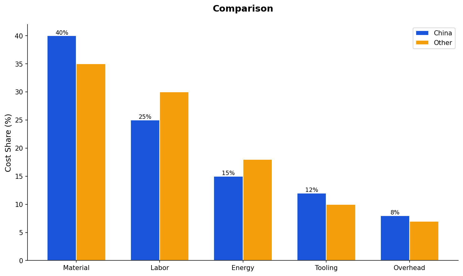
There is no single "correct" draft angle, because draft is a function of how the metal behaves on cooling and how the tool releases. Here's the working range for each process. Treat the low end as "achievable with a good tool and a cooperative geometry" and the high end as "safe default for a first quote."
| Process | Typical alloys | Outside walls | Inside walls / cores | What drives the number |
|---|---|---|---|---|
| Sand casting, hand rammed | Iron, steel, aluminum | 1.5°–3° | 2°–3° | Manual draw, mold rigidity |
| Sand casting, machine molded | Iron, steel, aluminum | 1°–1.5° | 1.5°–2° | Pattern draw mechanism, sand strength |
| Investment casting (lost wax) | Steel, stainless, superalloy | 0.5°–2° | 1°–2° | Wax pattern flexibility, shell integrity |
| Aluminum / magnesium die casting | A380, A360, ADC12, AZ91 | 1°–2° | 2°–3° | Hot metal shrinkage onto cores, ejection force |
| Zinc die casting | Zamak 3, Zamak 5 | 0.25°–0.5° | 0.5°–1° | Low shrinkage, high thermal conductivity |
| Permanent mold / gravity | Aluminum, some copper alloys | 1.5°–3° | 2°–4° | Metal mold, no collapsibility |
| Low-pressure die casting | Aluminum wheels, structural | 1.5°–2.5° | 2°–3° | Metal tool, controlled fill |
| Lost foam | Aluminum, iron | 1°–2° | 1.5°–2° | Foam pattern extraction, coating thickness |
Three things worth pulling out of that table, because they're where buyers get blindsided:
Zinc is a different animal. If you're sourcing a Zamak part and your drawing was written for aluminum die casting, you're over-drafting by a factor of two or more. That is not a manufacturing problem — it's a design problem, and it silently changes wall thickness on every drafted face. Zinc's low shrinkage and high thermal conductivity mean the part practically falls out. 0.25° is not a typo.
Investment casting buys you the smallest draft. The wax pattern is flexible, and the ceramic shell is destroyed after each pour. That freedom is real but it has a limit — below about 0.5° you start losing dimensional control because the wax can deform during handling. If your investment casting supplier offers 0.25°, that's a signal they're either very good or very optimistic.
Inside walls always need more than outside walls. Every row in that table shows it. There's a reason, and it's the single most common thing buyers miss.
The Depth Rule That Beats Every Table
A fixed draft angle is fine for shallow features. Once you go past roughly 75 mm of depth, the tables stop being useful and geometry takes over.
The reason: friction between the casting and the tool accumulates along the draw direction. The contact area grows with depth. At some point, a constant angle means the retaining force at the deepest section exceeds what the ejector pins can push without marking the part.
The working rule most experienced toolmakers apply — and you can hold them to this — is roughly:
| Feature depth | Minimum draft per side | Notes |
|---|---|---|
| Up to 25 mm | 1° | Standard. Anything less needs a reason. |
| 25–75 mm | 1.5° | Watch wall thickness drift on thin ribs. |
| 75–150 mm | 2°–2.5° | Consider stepped draft. |
| Over 150 mm | 2.5°–3° | Stepped or broken draft, or redesign the feature. |
Stepped draft is worth knowing about because it lets you have a steep wall where you need it and a generous angle where you don't. Instead of one continuous 3° taper over 200 mm — which moves your wall 10.5 mm — you break the wall into two or three sections. The top 60 mm gets 3° so release breaks cleanly, and the lower sections get 1° to 1.5° because the part has already released. Net movement drops, wall thickness holds, and the tool still ejects.
If a supplier proposes stepped draft on a deep part, that's a good sign. They've thought about ejection instead of just applying a default angle.
Texture, Inner Walls, and the Two Adjustments Most Drawings Miss
Two corrections get skipped on the majority of drawings I see, and both of them show up as defects rather than as design errors.
Adjustment one: surface texture eats your draft
A shot-blasted, etched, or coarse-cast surface is not a smooth surface. Every peak and valley adds drag along the draw path. If your drawing calls out a surface texture and a minimum draft angle, you've created a conflict the tool shop has to resolve — usually by adding draft you didn't budget for.
The rule of thumb circulating in tooling shops: add about 1° of draft for every 0.001 in. (0.025 mm) of texture depth. It's a conservative figure borrowed from injection molding, but die casters and investment casters apply the same logic to blasted and chemically etched cavities, because the physics is identical — texture increases friction.
Practical translation for a buyer:
- As-cast, no texture → use your table numbers
- Light blast, up to 0.025 mm texture → add 0.5°–1°
- Heavy texture or leather grain, 0.05–0.1 mm → add 1.5°–3°
If your part has a cosmetic texture callout, put the adjusted draft on the drawing. Otherwise the texture and the draft get resolved in the tool shop, and the resolution is never in your favor.
Adjustment two: inner walls need more draft than outer walls
When molten metal cools around a core, it shrinks onto it. The casting grips the core. To break that grip, the core needs an escape route — and that means more taper.
The industry convention is roughly 1° more draft on internal surfaces than external ones. Sand casting outside walls at 1.5° means inside walls at 2.5°–3°. Die casting outside at 1.5° means inside at 2.5°–3°. Investment casting outside at 1° means inside at 2°.
This is where drawings written by people who've only done CNC machining tend to fail. A vertical or near-vertical internal rib looks fine in CAD. In the mold, it's a core pin surrounded by shrinking aluminum, trying to pull itself out of a hole that's clamping down on it. Parts come out with scuffed surfaces, cracked ribs, or cores that pull. Every one of those outcomes lands on your invoice, not the foundry's.
Two rules to carry into design review:
- Internal ribs and bosses get 1° more than the adjacent outer wall, minimum.
- Deep internal features need more than shallow ones — apply the depth table to the core, not the cavity.
Where Draft Collides With Your Tolerance Stack
Draft changes dimensions. That sounds obvious written down, but it catches people because the change is gradual and CAD makes it invisible unless you look for it.
Concretely: a 3° draft over 100 mm moves the wall 5.24 mm. If your drawing calls out a ±0.2 mm tolerance on a dimension measured across that drafted wall, you've specified something the process cannot hold — not because the foundry is sloppy, but because the surface is a cone, and a cone has a different dimension at every point along it.
Where this bites hardest:
- Mating faces on drafted walls. Two castings that slide together along a drafted surface have a variable gap. The gap is tight at the bottom of the draw and loose at the top.
- Wall thickness on deep ribs. A nominal 3 mm rib with 2° draft at 150 mm depth is 3 mm at the base and a very different number at the tip. Thin-wall die casting lives or dies on this.
- Bolt bosses and hole positions. A boss with draft has a moving centerline if the datum is on the drafted surface. Long assemblies with several drafted interfaces can stack that shift into a fit problem.
- Weight calculations. If your part is weight-critical and you modeled it with straight walls, adding draft adds material. On a large part that's real mass.
The fix is usually straightforward, but it has to happen before tooling:
- Move critical dimensions to flat faces, perpendicular datums, or machined surfaces
- Widen tolerances on drafted surfaces to reflect the taper
- Call out "no draft" on any surface where a vertical wall is genuinely required — and accept the side action that comes with it
- Ask the foundry to state draft in the DFM report so you can re-run your stack with real numbers
That last point is the one buyers skip. Approving a DFM report that says "draft added as required" tells you nothing. You need the number, per surface group, before you can re-check your stack.
Three Lines to Put on the Drawing Before You Send It
Everything above is analysis. This part is what you actually write down — because a draft callout that lives only in an email thread is not a specification. It's a hope, and hopes don't survive a change-order conversation.
Three lines. They take four minutes, and they close off most of the ways a draft dispute starts.
| Line | What it says | What it prevents |
|---|---|---|
| 1. Minimum draft, per surface group | "Minimum draft: 2° outside walls, 3° inside walls and cores, measured from the draw datum shown in View D." | The "we assumed you meant the default" conversation after T1 |
| 2. Texture allowance | "Draft values above exclude texture. Add 1° minimum to all blasted or etched surfaces." | Texture and draft fighting it out in the tool shop, in the supplier's favor |
| 3. Zero-draft callout | "Any surface on the draw path below 1° requires written confirmation of the release mechanism and its tooling impact." | Silent side actions appearing in the quote — or worse, after the quote |
The third line is the one that earns its keep. It converts a vague disagreement into a written answer: either the surface releases as designed, or you get the number — percent of tooling cost, weeks of schedule — before you sign anything. That's the difference between a design review and a bill you didn't authorize.
Template — plain-language version: "Minimum draft 2° on outside walls, 3° on inside walls and cores, measured from the datum in View D. Values exclude texture; add 1° to all blasted or etched surfaces. Zero-draft or under-drafted surfaces on the draw path require written confirmation of the release mechanism and its tooling and cycle-time impact before production tooling is released."
Paste it, adjust the numbers to your process, and move on. Most draft disputes are not technical disagreements. They're missing sentences.
Who Actually Pays When Draft Goes Wrong
This is the uncomfortable one, and it's the reason the drawing note matters more than the drawing itself.
When a tool needs rework after T1, cost usually lands according to who can point at what in writing. Not who was technically right. Here's how it tends to play out:
| Scenario | Who usually absorbs it | What shifts it |
|---|---|---|
| Drawing specifies draft; supplier undercuts it and T1 shows drag marks | Supplier | The written callout. Without it, this becomes a "mutual" cost split. |
| Drawing shows a zero-draft wall; supplier quotes without flagging the side action | You | A DFM report stating per-surface draft values. If their report says "draft applied" and nothing else, the assumption follows the drawing. |
| Draft is fine; the failure is texture-related drag | Usually you | Line 2 on the drawing. If texture allowance was never specified, the supplier meets the angle and you still get the defect. |
| Supplier requests more draft than the geometry needs; the tool is built to the larger angle; the part no longer fits | Whoever approved the change order | A written response to the change request, with the calculation attached. Approve nothing verbally. |
| Thin wall at depth under-fills; draft was within spec | Split, usually — and this is the one that hurts | Wall thickness and draft specified together, with a minimum wall callout at the deepest section. |
Nothing on that list is fixed in stone, and that's the point. Every row where "who pays" is uncertain is a row where the answer gets decided by whoever has the better paper trail. Ten minutes of drafting puts you on the right side of five of them.
Common Mistakes to Avoid
These are the ones that show up over and over in RFQ packages and T1 sample reviews.
1. Specifying an angle without a direction. "Draft 2°" is incomplete. Draft from what datum, in which direction, relative to which parting line? On a part with two draw directions, that note is ambiguous and will be interpreted however suits the tool shop.
2. Using the same angle inside and outside. Internal surfaces need about 1° more. Skipping this is the most common cause of ejection scuffing on internal ribs.
3. Forgetting texture. A textured part needs draft added on top of the geometric minimum. Two conflicting callouts on the same drawing means someone downstream makes a judgment call on your behalf.
4. Applying the table value to a deep feature. A 1° draft that works fine at 20 mm depth will fail at 150 mm. Use the depth table, or ask for stepped draft.
5. Tight tolerances on drafted surfaces. If the surface is a taper, the dimension moves. Pick a datum that doesn't move.
6. Zero draft "to save cost." Removing draft doesn't save cost — it moves cost. Zero-draft walls on the draw path require side actions, which typically add 15% to 40% to tooling and add cycle time on every part you'll ever run. On a 100,000-piece program, side actions are never the cheap option.
7. Approving a DFM report that doesn't state draft values. "Draft applied" is not a specification. Ask for a table: surface group, minimum angle, direction, datum.
8. Ignoring the draft on the parting line decision. Draft direction and parting line are the same decision made twice. If you choose the parting line after the draft, you'll redo the draft.
9. Leaving the draft callout out of the PO. The drawing is an attachment. If the PO doesn't reference the drawing revision, the revision that gets built is whatever the tool shop had open. Reference the revision number in the purchase order text, every time.
Auditing a Supplier's DFM Report: A 7-Point Checklist
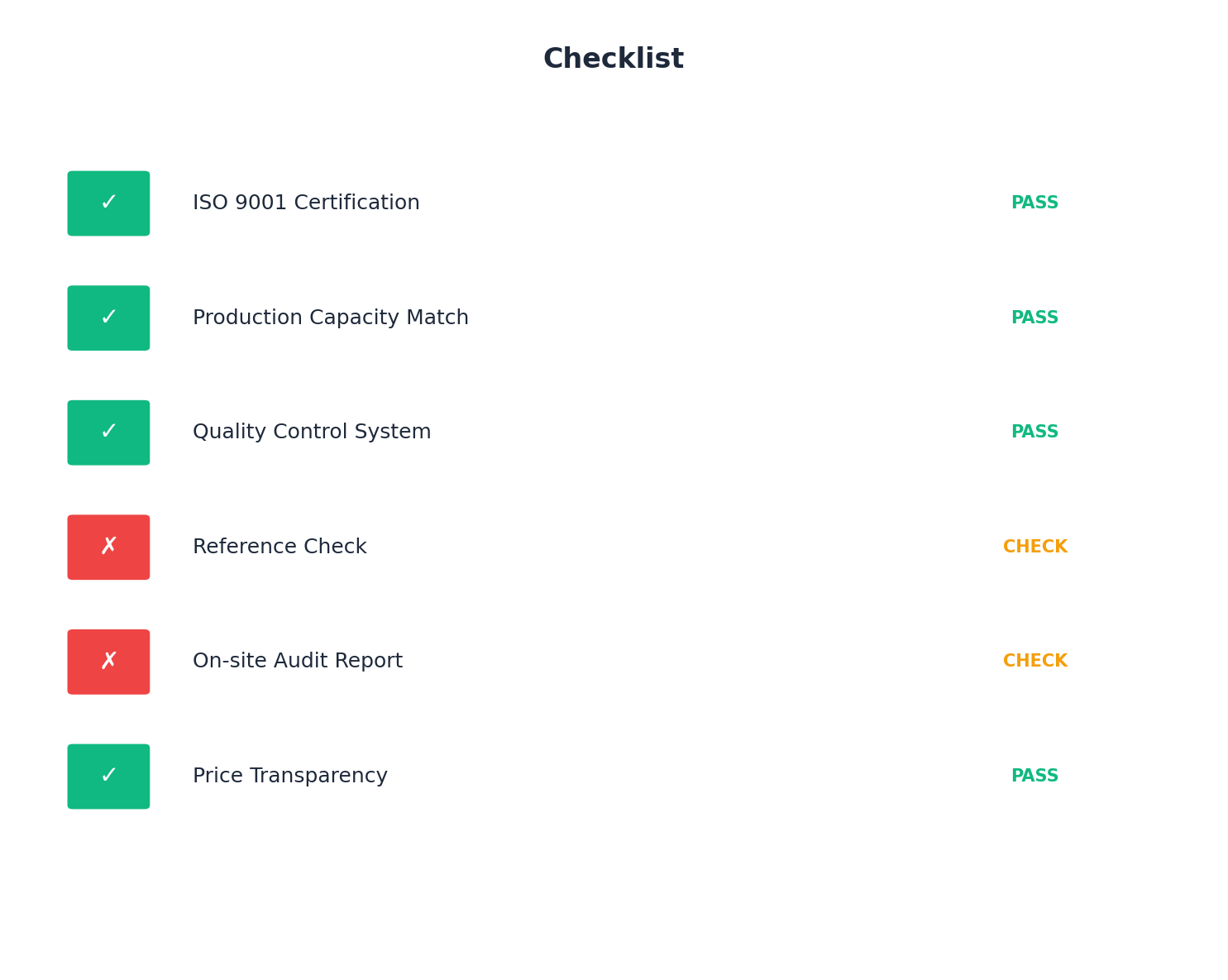
Run this against every DFM report before you approve. It takes about ten minutes and it's saved buyers considerably more than that.
| # | Check | What a failure looks like |
|---|---|---|
| 1 | Is draft direction stated for every draw? | Report shows angles but no direction or datum reference. |
| 2 | Are internal walls drafted more than external walls? | Single angle value applied across the whole part. |
| 3 | Is texture allowance added on top of geometric minimum? | Textured surfaces shown at the same angle as smooth ones. |
| 4 | Do features over 75 mm deep use stepped or increased draft? | Constant 1° applied to a 150 mm pocket. |
| 5 | Is there any negative or zero draft on the draw path? | Vertical walls shown without a side action callout. |
| 6 | Are critical dimensions measured off drafted surfaces? | GD&T datum placed on a tapered wall. |
| 7 | Are numeric draft values given per surface group? | "Draft added as required" with no table. |
One more thing on this list: ask the supplier to flag which changes are recommendations and which are requirements. Some DFM reports bundle cosmetic suggestions with hard process constraints, and treating a suggestion as a requirement can push you into unnecessary tooling cost. If a change is genuinely required for ejection, the supplier can explain the mechanism. If they can't, it's probably a preference.
What Bad Draft Costs You Downstream
Draft is nearly free at the design stage. Everywhere after that, it gets expensive.
The cost ladder, in order of what you'll actually pay:
- Design stage. Changing a draft angle in CAD. Minutes of work.
- Post-quote. A revised quote, a new tool design review, a schedule slip of one to three weeks.
- Post-tooling, pre-T1. Sparking or EDM work on the cavity, or weld and remachine. Tooling shops quote this in the thousands of dollars, plus the calendar time.
- Post-T1. If samples pass but produce marginal ejection, you inherit it as a permanent yield penalty. Scrap rates on thin-wall parts with inadequate draft can run into the low double digits, and that cost follows every unit for the life of the program.
- Post-launch. Field failures from under-filled sections or cracked ribs. This is the tier nobody wants to be in.
The asymmetry is what matters. Ten minutes of draft review versus a tool modification on a hardened die. The math isn't close.
FAQ
What is the standard draft angle for aluminum casting?
Aluminum die casting typically runs 1°–2° on outside walls and 2°–3° on inside walls. Sand casting runs 1.5°–3° outside and 2°–3° inside. Features deeper than 75 mm usually need stepped or increased draft rather than a single fixed angle.
Can a cast part have zero draft?
Only with a side action, a collapsible core, or a machined feature after casting. Any zero-draft surface on the draw path will drag, gall, or crack on ejection. If your drawing shows a vertical wall on the parting-line draw, expect either a change order or a rejection.
How much does draft angle add to part cost?
Draft itself costs almost nothing. The absence of draft is what costs money. Insufficient draft forces a tool into side actions, which typically adds 15%–40% to tooling and adds cycle time on every part. It also increases scrap, sometimes into the double digits on thin-wall work.
Does draft angle change dimensional tolerance?
Yes. A drafted wall is a taper, so a dimension measured along it changes with depth — a 3° draft over 100 mm moves the wall 5.24 mm. Put tight tolerances on flat faces or perpendicular datums, and widen tolerances on drafted surfaces.
Should you specify draft angle on the drawing or leave it to the foundry?
Specify the minimum you'll accept, plus the datum it's measured from. Leaving it blank means the foundry applies its own default, which may not match the tolerance stack your design assumed. One note on the drawing prevents most of these disputes.
Who pays when a draft problem forces tool rework?
Usually whoever has it in writing. If the drawing states a minimum draft and the tool undercuts it, the rework sits with the supplier. If the drawing shows a zero-draft wall and the DFM report never flagged the side action, it usually sits with you. The three drawing lines above are what keep it on the supplier's side of the table — and the reason to get the per-surface draft values in the DFM report before you approve tooling.
Next Steps
Before you approve your next casting drawing, do three things:
- Run the depth table against every feature deeper than 25 mm in your part. Flag anything using a flat 1°.
- Check internal walls against external walls. If they're the same number, you have a gap.
- Send the DFM report you received through the seven-point checklist above. If any line comes back blank, ask for the number in writing.
Then write the three lines onto the drawing and reference that revision in the PO. It's the cheapest insurance in the whole tooling program, and it takes less time than reading this section took.
If you want a second set of eyes on a drawing or a DFM report before you commit to tooling, submit it for review. You'll get the draft values laid out per surface group, the depth issues flagged, and a straight answer on whether the side actions in the quote are genuinely required.